PIC-GSM


| Price | 89.95 EUR |
|---|---|
| 10 - 49 pcs | 80.96 EUR |
| 50 - 10000 pcs | 71.96 EUR |
The purpose of this board is to allow the development of remote control applications. Using PIC-GSM you can easily monitor and control your home from everywhere with your GSM cell phone. You can switch on and off relays remotely by SMS. You can monitor the status of your GPIOs or toggle them. You can establish a call to the GSM module and speak or listen on the audio channel of the board. You can monitor the temperature from several digital remote temperature sensors. The build-in GSM module has an on-board antenna and it allows you to use it as a GSM or a GPRS meaning that you can also use this module as a GPRS modem connected to your computer. A panic button and alarm inputs can dial your phone or send you a SMS message to report for an alarm.
FEATURES
- ICSP/ICD connector for programming with and debugging with PIC-ICD2-POCKET or PIC-KIT3
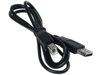
- USB 2.0 type B connector allow board to be interfaced to PC host.
- GSM/GPRS module 900/1800/1900Mhz (2G)
- Li-ion backup battery
- PIC18F97J60-I/PT
- GSM Audio In and Out
- Quartz crystall 20Mhz
- Two relays 10A/250VAC
- Two digital inputs
- Analog input
- Temperature sensor
- 5V voltage regulator
- EXT connector for available GPIO
- Four mounting holes 3,3 mm (0,13")
- FR-4, 1.5 mm (0,062"), red soldermask, white silkscreen component print
- Dimensions 100x80 mm (3,9x3,15")
DOCUMENTS
- PIC-GSM.pdf - User's manual
- GSM/GPRS module AT commands set
- Understanding PIC WEB boards and Microchip TCP-IP stack tutorial
HARDWARE
SOFTWARE
- PIC-GSM example software with Microchip TCP/IP stack 5.42 for MPLAB 8.xx and MPLAB X
- PIC-GSM open source remote control software with Microchip TCP/IP stack 5.00
- There is a known issue with C18 V3.37.01 & TCIP/IP V5.31 (or TCIP/IP V5.00). The fastest workaround is to use the previous C18 (v3.34) until the next C18 version is released. Another work around is to use this p18f67j60.h instead of the one provided by the newer compilers
FAQ
- The PIC-GSM module was working fine but I decided to test how it would behave without the battery. I changed the jumpers as per datasheet but now it doesn't work. What might be the reason?
- The battery might be completely out of charge - let it recharge a bit and attempt again. To switch the positions of SMT jumpers you would need additional tools and further experience in electronics. If you dobut your skills do not attempt to change the jumpers. Double-check if all SMT jumpers have been closed (pads soldered) or opened (wire between pads is cut and no soldering residue is present) as per datasheet. IMPORTANT! Always ensure that the three jumpers 4V_E, 4V and 5V_CHG_E jumpers are moved together. If you leave one of those jumpers unchanged and you power the board you would damage the GSM component.


